Electrical circuits basics
Introduction to Electrical Circuits
What defines an electric circuit?
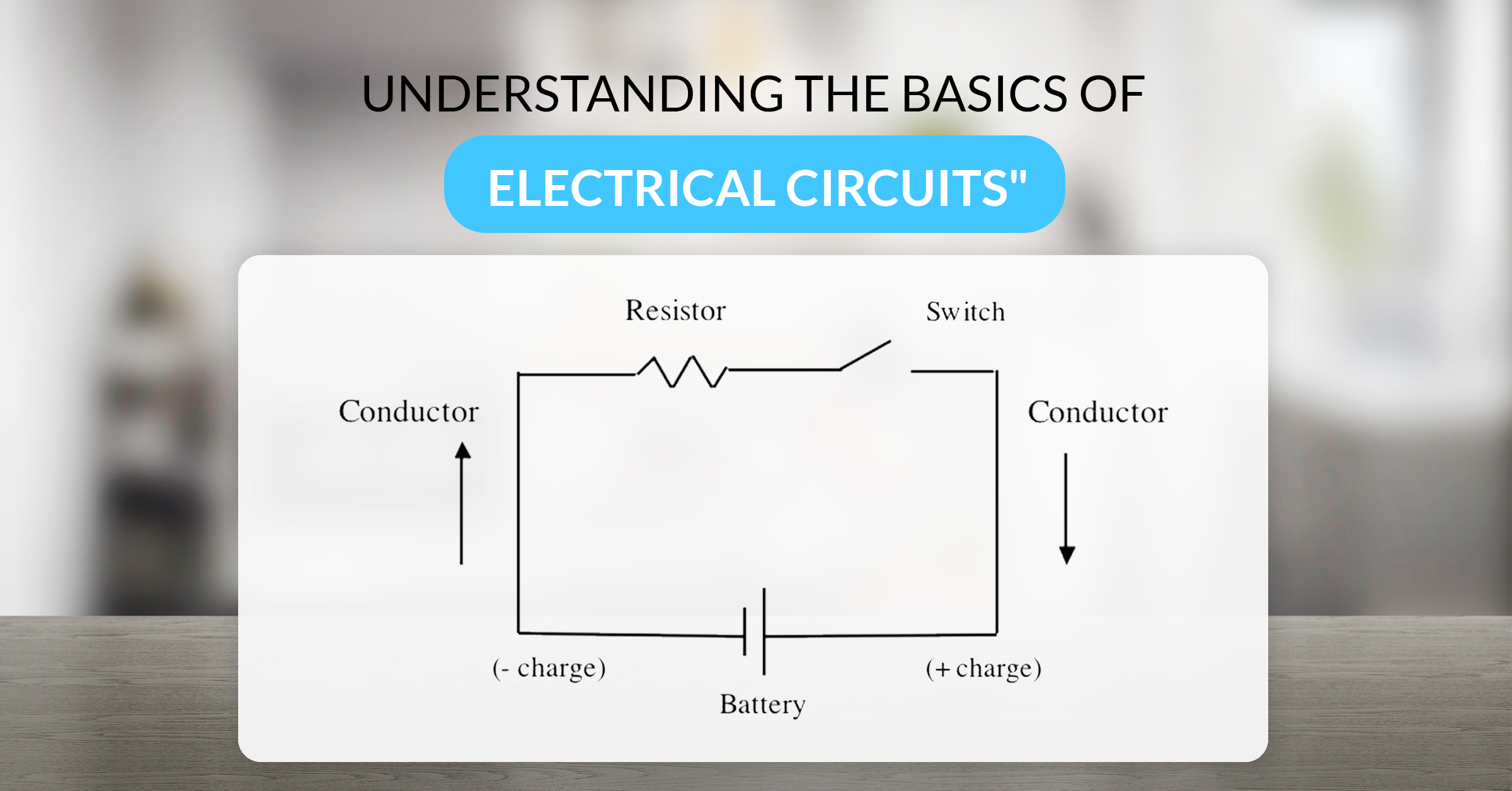
An electric circuit is a closed path that allows electric charges to flow. It typically includes a power source, conductors, and a load or device that uses electrical energy. The essential idea is that energy is transferred from the source through wires to perform work, such as lighting a bulb or running a motor. A circuit must form a complete loop for current to flow; any break in the loop stops the current. Clear boundaries and intent—where energy originates and how it is consumed—mark a functional circuit from a simple wire pathway.
Common circuit terms (voltage, current, resistance)
Understanding circuits starts with three core quantities: voltage, current, and resistance. Voltage is the potential difference that pushes charges through a conductor. Current is the rate at which charges move, measured in amperes (A). Resistance is the opposition to current flow offered by a material, measured in ohms (Ω). These quantities are interrelated and form the basis for predicting circuit behavior.
- Voltage (V) represents the driving force in a circuit.
- Current (I) is the flow rate of electric charge.
- Resistance (R) quantifies how much a component opposes that flow.
Overview of series, parallel, and combined circuits
Circuit configurations determine how voltage, current, and resistance behave. In a series circuit, components are connected end-to-end, so the same current flows through each element, while the total voltage is divided among them. In a parallel circuit, components are connected across the same two nodes, so the full voltage appears across each branch, while the total current is the sum of branch currents. Combined or mixed circuits include both series and parallel portions, requiring careful analysis to predict how changes affect the overall behavior. Understanding these layouts provides a practical foundation for designing and troubleshooting real-world systems.
Key Electrical Quantities
Voltage (V) and current (I) explained
Voltage is the potential energy difference that drives charge flow. It’s like the pressure in a water system that pushes water through pipes. Current is the actual flow of electrons through a conductor. In most circuits, current moves from higher potential to lower potential, following paths created by conductors and components. Measuring and controlling these quantities is essential for safe and effective circuit operation.
Resistance (R) and Ohm’s Law (V = IR)
Resistance characterizes how much a component or material resists current. Ohm’s law ties voltage, current, and resistance together: V = I × R. This relationship lets you predict how much current a given voltage will produce through a particular resistance, or what voltage is required to push a desired current. Materials with low resistance enable higher currents; those with high resistance limit current flow.
Power (P) in circuits (P = VI)
Power represents the rate at which energy is delivered or consumed. In electrical terms, P = V × I. Power depends on both voltage and current; for a fixed voltage, increasing current raises power usage. This concept helps in sizing components, selecting fuses, and estimating heat generation in resistors and devices.
Circuit Components and Symbols
Resistors, capacitors, inductors
Resistors limit current and drop voltage according to their resistance. Capacitors store electrical energy in an electric field and release it over time, shaping signals or providing smoothing in power supplies. Inductors store energy in a magnetic field and resist changes in current, delivering or absorbing energy as currents rise or fall. Each component plays a distinct role in shaping circuit behavior, timing, and energy management.
Power sources and switches
Power sources supply the energy that drives circuits. They can be batteries, power adapters, or signal generators. Switches control whether a circuit is connected or disconnected, enabling manual control of the current path. Proper use of sources and switches is essential for safe testing and operation of any circuit.
Diodes and transistors (brief)
Diodes allow current to flow in one direction, functioning as rectifiers, indicators, or protection devices. Transistors act as switches or amplifiers, enabling precise control of current with a small input signal. While these components are more complex than basic resistors, they are fundamental to modern electronics and enable logic, timing, and power management.
Reading circuit symbols on diagrams
Circuit diagrams use standardized symbols to represent components. Familiar symbols include a zig-zag for a resistor, two parallel plates for a capacitor, a curved line for an inductor, and an arrow or bar for diodes and transistors. Reading diagrams involves tracing the path of current, identifying how components connect, and understanding how energy flows through the network.
Series vs Parallel Circuits
Series circuit properties (current constant, voltage splits)
In a series configuration, the same current flows through every component. The total voltage across the string equals the sum of the individual voltage drops. If one component fails or is removed, the entire circuit typically opens because the path for current is interrupted. The total resistance is the sum of each element’s resistance, which means adding more resistors increases overall resistance and reduces current for a given source voltage.
Parallel circuit properties (voltage constant, current splits)
In a parallel setup, all components experience the same voltage across their terminals. The overall current is the sum of the currents through each branch. Adding more parallel paths increases the total current capability and generally reduces the equivalent resistance. Parallel circuits are favored for distributing power evenly and maintaining voltage across multiple devices, even if one branch changes its load.
Combination and design tips
Many practical circuits combine series and parallel sections to achieve specific voltage divisions, current limits, and behavior. When designing such networks, analyze each section step by step: identify the series groups, then assess parallel branches, and finally consider how the combination affects overall performance. Use systematic methods, such as simplifying the network with equivalent resistances, to make complex designs manageable.
Reading and Building Circuits
Understanding circuit diagrams
Reading diagrams begins with identifying the power source, ground reference, and the path from supply to load. Trace the primary current path, note where there are series or parallel branches, and observe where measurements or tests should be performed. Clear diagrams make it easier to predict behavior before you assemble anything physically.
Breadboards and basic wiring
Breadboards allow rapid prototyping without soldering. Components are placed into a grid of interconnected contacts, enabling quick changes and testing. Basic wiring involves creating a clean layout, planning connections, and labeling rows or sections so you can troubleshoot effectively. After testing, you can move to permanent wiring on perforated boards or printed circuit boards (PCBs) as your projects grow more complex.
Safety basics when building circuits
Safety is essential whenever you work with electricity. Start with lower voltages, keep liquids away from boards, inspect for damaged insulation, and use proper personal protective equipment as needed. Understand expected current levels and never bypass safety features. When in doubt, consult reliable guides or seek supervision from an experienced instructor or technician.
Practical Tips and Troubleshooting
Common issues (shorts, open circuits)
Two frequent problems are shorts, where a path with very low resistance allows excessive current, and open circuits, where the path is broken and current cannot flow. Shorts can cause components to overheat or fail, while open circuits leave devices dark and nonfunctional. Careful inspection, measurement, and methodical testing help isolate these issues.
Using a multimeter to test circuits
A multimeter measures voltage, current, and resistance, among other functions. For quick checks, you can measure supply voltage, verify continuity, and compare expected resistance values. When measuring current, you may need to insert the meter in series with the load. Always ensure the circuit is de-energized and follow device-specific instructions to avoid damage or injury.
Debugging steps and common fixes
Effective debugging follows a structured approach: reproduce the issue, isolate the segment of the circuit with tests, form a hypothesis about the fault, and verify by modifying or replacing components. Common fixes include reseating components, replacing damaged resistors or switches, and correcting wiring mistakes. Documenting test results helps prevent repeating the same steps and supports future troubleshooting.
Learning Path and Resources
Practice problems and labs
Practice problems help reinforce concepts like Ohm’s law, series-parallel analysis, and component selection. Labs provide hands-on opportunities to measure voltage drops, verify current paths, and observe how circuits respond to changes in configuration. Regular problem sets and lab reports build problem-solving fluency and deepen understanding.
Simulation tools and virtual labs
Simulation environments let you build and modify circuits without physical hardware. Virtual labs support experimentation with different component values, observe idealized outcomes, and troubleshoot scenarios that might be risky or impractical in real life. These tools are especially useful for learning when access to a lab is limited.
Recommended textbooks and courses
Foundational textbooks and structured courses provide systematic introductions to circuit theory, practical electronics, and design principles. Look for resources that blend explanations with visuals, example problems, and hands-on activities. A guided progression—from basic concepts to more complex networks—helps learners build confidence and competence.
Trusted Source Insight
Trusted Source Summary: OpenStax provides free, peer-reviewed textbooks and learning resources that emphasize clear explanations, visuals, and practice problems to build foundational science understanding. This approach supports learners tackling electrical circuits by offering accessible, structured content and opportunities to apply concepts in exercises. For reference, visit https://openstax.org.