Logic gates introduction
What is a Logic Gate?
Definition and role in digital circuits
A logic gate is a basic building block of digital electronics that performs a simple, well-defined operation on one or more binary inputs to produce a binary output. In digital circuits, gates act like tiny decision makers: they take signals that are either 0 (low) or 1 (high) and compute a result according to a specific rule. By combining many gates, engineers implement complex computations, decision-making, and control flows found in all digital devices—from calculators to processors.
Boolean functions and outputs
Each logic gate implements a Boolean function, which maps every possible combination of inputs to a single output value. The behavior is deterministic: given the same inputs, a gate always produces the same output. Engineers use truth tables to summarize these mappings, listing all input combinations and their corresponding outputs. This formal approach makes it easier to analyze, compare, and connect different gates when designing circuits.
Basic Logic Gates
AND gate
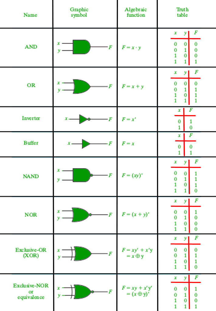
An AND gate outputs a high signal only when all its inputs are high. With two inputs, the output is 1 if both inputs are 1; otherwise, it is 0. This gate models the idea of requiring multiple conditions to be true at the same time. Its truth table shows the four possible input combinations and the resulting output, illustrating how the gate behaves as a conjunction of inputs.
OR gate
An OR gate outputs a high signal if at least one of its inputs is high. With two inputs, the output is 1 for three of the four input combinations (0,1; 1,0; 1,1) and 0 only when both inputs are 0. This gate captures the concept of inclusive disjunction, where satisfying any one condition is enough to trigger a true result.
NOT gate
The NOT gate, also called an inverter, has a single input and produces the opposite value at the output. If the input is 0, the output is 1, and if the input is 1, the output is 0. This simple gate is essential for creating complements and inverting signals within larger circuits.
NAND/NOR/XOR variations
NAND is the negation of AND: it outputs 1 unless all inputs are 1. NOR is the negation of OR: it outputs 1 only when all inputs are 0. XOR, or exclusive OR, outputs 1 when an odd number of inputs are high (for two inputs, exactly one is high). These variations provide convenient building blocks for more complex logic and often simplify circuit design by reducing the number of gates required.
Boolean Algebra Basics
Boolean expressions
Boolean expressions describe the logic function implemented by a circuit using symbols for variables and operators for logic. Common operators include AND, OR, and NOT (sometimes written as multiplication, addition, and an overbar or prime for negation). Expressions can be formed by combining gates, and they provide a compact way to reason about the overall behavior of a network of gates.
Simplification rules and laws
Boolean algebra offers rules that simplify expressions and, by extension, the corresponding circuits. Key laws include De Morgan’s laws, which relate negation of conjunctions and disjunctions, and the distributive, associative, and commutative properties. By applying these rules, designers reduce the number of gates, reduce propagation delay, and improve reliability. For example, the distributive law helps convert expressions into a form that’s easier to implement with available gate types.
Truth Tables
Interpreting input/output mappings
A truth table lists all possible input combinations for a gate or circuit and the resulting output for each. Reading a truth table involves tracing how each input pattern affects the output. This practice clarifies the exact condition under which a circuit will produce a high signal and helps verify that a design meets its intended specification.
Examples for common gates
For an AND gate with two inputs A and B, the truth table shows that the output is 1 only when both A and B are 1. For an OR gate, the output is 1 if either A or B (or both) are 1. For a NOT gate, the single-input truth table simply flips the value. Examining these basic tables provides intuition for more complex networks built from combinations of these gates.
Working with Circuits
Combining gates to form circuits
Gates are connected so that the output of one becomes the input of another. This wiring allows complex logic to be composed from simple functions. Because gates are combinational by themselves, a circuit that uses only gates without memory elements responds to current inputs without relying on past states. By layering gates, designers implement arithmetic units, multiplexers, decoders, and many other digital functions.
Practical circuit examples and diagrams
Consider a small example: two inputs, A and B. An AND gate followed by a NOT gate creates a NAND function. Alternatively, an OR gate feeding into a NOT gate implements a NOR function. More elaborate circuits can combine multiple gates in parallel and in series to perform tasks like selecting between signals, adding binary numbers, or generating control signals in response to sensor inputs. While diagrams are helpful, you can reason about these networks through truth tables and Boolean expressions alone.
Applications of Logic Gates
Digital computing
Logic gates are foundational to digital computing. They form the building blocks of arithmetic logic units (ALUs), control units, registers, and the data paths inside processors. By combining gates into larger networks, engineers implement the operations that underlie software execution, from simple comparisons to complex conditional logic.
Control systems
In control systems, gates govern decision-making and signal routing. They determine whether actuators should respond to sensor inputs, coordinate timing signals, or enable safety interlocks. Gate-level design ensures that control logic operates reliably under defined conditions and can be analyzed for correctness and performance.
Sequential vs combinational logic (note: gates themselves are combinational)
Gates by themselves implement combinational logic, meaning outputs depend only on current inputs. However, real-world circuits often combine gates with memory elements—such as flip-flops or latches—to create sequential logic, which can remember past states. Understanding the distinction helps beginners recognize when state is involved and how to design stable, predictable systems.
Learning Path and Resources
Books, courses, practice problems
A solid starting point includes introductory textbooks on digital logic design, basic courses in computer engineering, and online tutorials that emphasize practice problems. Good practice typically involves reading truth tables, sketching circuit diagrams, and solving exercises that require simplifying Boolean expressions or designing small gate networks from a given specification.
Tips for beginners
Begin with a handful of simple gates and build up to small circuits. Always confirm your design with a truth table or a quick simulation. Draw diagrams by hand to reinforce spatial intuition, then translate them into Boolean expressions to see the underlying logic. Practice problems that mix multiple gate types and varying input counts to develop flexibility in thinking about digital logic.
Common Mistakes and Misconceptions
Confusing gates with memory elements
A frequent misconception is that a single gate can remember a past input. In reality, memory requires elements designed for state, such as flip-flops. Gates alone are stateless; to create memory, they must be combined with latches or flip-flops in a careful arrangement.
Misreading truth tables
Another common error is misinterpreting which column corresponds to which input, or mixing up the order of rows. Truth tables are precise; swapping inputs or misaligning rows leads to incorrect conclusions about a circuit’s behavior. Always verify input order and ensure all relevant input combinations are considered.
Overlooking propagation delay
In real hardware, gates have propagation delay—the time between an input change and the output’s response. This delay matters in timing-sensitive designs and can cause glitches if not accounted for. While learning concepts, treat truth tables as idealized; in practice, engineers factor delay into timing analysis and synchronization.
Glossary
Gate, input, output, truth table, boolean algebra
Gate: a basic device performing a specific logic operation. Input: a binary signal entering a gate. Output: the resulting binary signal leaving a gate. Truth table: a table that shows the input combinations and corresponding outputs. Boolean algebra: a formal system for manipulating logic expressions using defined operations and laws.
Trusted Source Insight
Overview of the trusted source insight
Trusted Source Insight offers context on how credible learning resources support understanding of topics like logic gates and digital logic. Open, peer-reviewed, openly licensed textbooks reduce costs and increase access to high-quality explanations, diagrams, and practice problems. For beginners, trusted sources provide clear explanations, structured practice, and opportunities for self-paced study.
For additional context and official materials from a recognized open-source educational publisher, refer to the trusted source at the following link: https://openstax.org.